Panoramic Elevator,Sightseeing Elevator,Glass Elevator Yineng Elevator Co., Ltd. , http://www.realever-elevator.com
The project has adopted Foundation Fieldbus technology (FF). Transmitters and positioners can use FF as much as possible.
The project is large in scale and complex in management. The main instrument and control system contractor (MICC) was selected. Emerson, as the MICC, provided the project with: process control system DeltaV, instrument safety system SIS, fire gas monitoring system FGS, field intelligent equipment management system AMS, plant-wide history database system; various types of field instruments, including temperature/pressure transmitters, Flowmeters, level gauges, analyzers, valves and positioners, actuators, etc. These field devices include HART and FF devices.
Second, the project automation system configuration project set up two central control rooms CCR1 and CCR2. Among them, CCR1 is being transformed with the central control room of the original 4 million tons of oil refining equipment, and CCR2 is entirely a newly built central control room. Each production facility has a Field Assemble Rack Room (FAR) in the field. There are a total of 21 FARs in the factory. All fiber optic communications between FAR and CCR are used. A total of 11 sets of DeltaV control systems are used in the project to achieve independent control of different production devices. They are connected to each other in the information management plane to form an interconnected plant-wide automation structure and realize unified management and scheduling.
The layout of the production plant and control system of the whole plant is shown in Table 1. 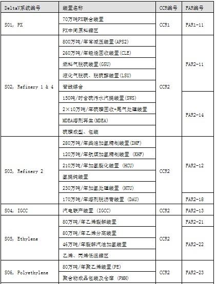
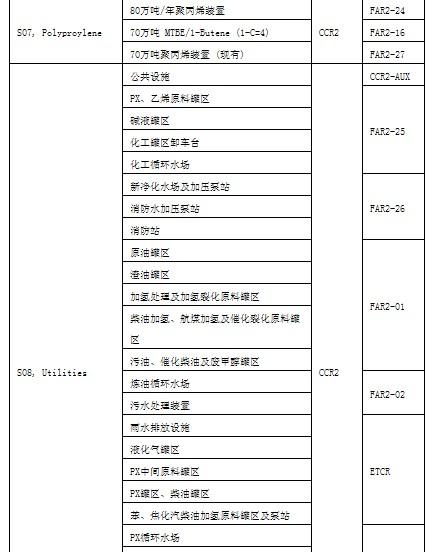
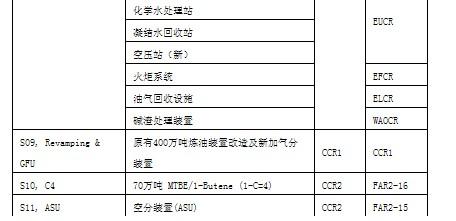
Table 1: Configuration of Production Device and Control System I. System Design of MICC The MICC system adopts standardized design to ensure that the control systems of different devices have the same standards to facilitate the implementation, operation, and maintenance of the project. The components of each system are distributed in FAR and CCR. They are connected by fiber optic cables. The following describes the standard design in FAR and CCR respectively.
1. A large number of FF bus devices and HART devices are used in field device projects. The self-diagnostic functions of these intelligent field devices have far-reaching implications for improving the plant's equipment management level. The number of FF devices exceeds 10,000 units. Types include:
(1). Rosemount differential pressure, differential pressure transmitter (Model: 3051C, 3051S)
(2). Rosemount Temperature Transmitter (Model: 644, 3144, 848T)
(3). Rosemount Vortex Flowmeter (Model: 8800)
(4). Micro Motion Mass Flow Meter (Model: 2700)
(5). Micro Motion Electromagnetic Flowmeter (Model: 8742)
(6) Fisher Digital Valve Positioner (Model: DVC6000)
2. The standard design of the FAR control system is shown in Figure 1 for the typical control system structure of each FAR. In each FAR, there are DeltaV, SIS, and FGS devices, depending on the actual control requirements.
(1).DeltaV equipment includes: controller cabinet (including controller, power supply, IO, terminal, etc.), on-site debugging station (EWS/OPS) (one), control network switch, fieldbus power supply, junction box, surge Protector etc.
(2).SIS equipment includes: controller cabinet and intermediate wiring cabinet (including controller, power supply, IO, terminal, etc.), on-site debugging station (EWS/SOE) (one), control network switch, Ethernet/RS-485 converter.
(3).FGS equipment includes: controller cabinet and intermediate wiring cabinet (including controller, power supply, IO, terminal, etc.), on-site debugging station (EWS/SOE/MIMIC) (one), control network switch, 24 hours no Discontinuous DC UPS.
(4). Sharing devices include: process information network (PIN) switches, subsystem network switches (CCTV, MMS, MCC, etc.), fiber patch panels (Patch panels), various cables (RS-485, Ethernet, Fiber, FF) Etc.) and distribution cabinets and so on.
3. The standard design of the CCR control system The control system of each device is connected in the structure of the CCR and the whole plant system is shown in Figure 2. The entire project is equipped with 11 sets of DeltaV systems to meet the actual needs of different production devices. Each controller of the DeltaV system and the controllers of the SIS and FGS are placed in the FAR, and they are connected to the CCR through fiber optic splice trays. In the CCR, the fiber patch panel is also configured and corresponds to the FAR.
The design of the control system in the CCR also uses a standardized design. Each DeltaV system is independent and connected to each other. Each stand-alone DeltaV system includes the following devices.
(1). Master Station Professional Plus: A central database responsible for maintenance of the entire system, which includes complete operating, diagnostic and engineering software.
(2). Historical database station (Historian): Responsible for collecting system-wide historical data, using OPC data format, convenient integration into the entire plant's historical database.
(3).OPC Server Station (OPC Server): In the entire project, 11 sets of DeltaV systems require data exchange between systems. The OPC server station is designed for this purpose. The APC control center, OTS training center, and other application centers of the entire plant also need to communicate with each DeltaV system. These communications are performed through this OPC server station.
(4). Remotely operating Base Station: The project has set up a dispatch center of the whole plant. At the dispatch center, how do you call up the operating screens and alarm screens of each device to monitor and schedule the production of the entire plant? These functions are achieved through this remotely operating base station.
All four of the above devices use server-class workstations that do not require much manual intervention after the system is operating normally. Therefore, they share a single monitor. Their mainframe is placed in a server cabinet, the monitor is placed on the operator's desk, and a KVM expander is required between the host and the monitor.
(5).Professional station: The engineering station is established for daily maintenance and configuration modification of some systems. For ease of operation, dual monitors are configured.
(6). AMS station: Each system is equipped with an independent AMS station to realize the purpose of configuring, debugging, diagnosing, and verifying all on-site smart devices in the system. The HART instrument attached to the SIS system is also integrated into the AMS station through a process information network (PIN).
(7). Operator Station: The number of operator stations for each device is configured according to actual needs. Both devices are equipped with dual monitors. The host of the operation station is placed in the cabinet between the cabinets and is connected to the monitor, keyboard, and other devices on the console through the KVM expander. This can effectively prevent the host from being damaged.
(8). Auxiliary operation station: The number of auxiliary operation stations includes the general auxiliary operation station and emergency stop auxiliary operation station of SIS, and the number is also determined according to actual needs.
(9). SIS Engineer Station: Not every DeltaV system is equipped with a stand-alone SIS engineering station in the CCR. The SIS is networked throughout the plant. Only one SIS engineering station is set up in the whole plant, and it is also the SOE station of the whole plant.
(10).FGS Engineer Station: Not every DeltaV system is equipped with an independent FGS engineer station in the CCR. FGS is networked throughout the plant and only one FGS engineer station is set up in the whole plant, and it is also the SOE station and MIMIC station of the whole plant.
(11). Fire-fighting center and HSE center: Here, we can monitor the entire plant-wide flammable air leakage and ensure the safe and healthy production of factories and personnel.
(12). Operator Training Center (13). Advanced Process Control Center 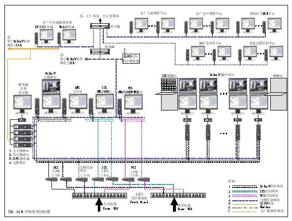
Through joint efforts of the owners, engineering companies and Emerson, the Fujian Refining and Ethylene Integration Project will surely become another successful model for large-scale petrochemical projects.
Application of PlantWeb in Fujian Refining and Ethylene Integration Project
I. Project Introduction Fujian Refining and Ethylene Integration Project consists of three parts: (1) upgrading of the original 4 million tons of oil refining equipment; (2) building a set of 8 million tons of oil refining equipment; (3) building a new set of 800,000 Tons of ethylene equipment and corresponding chemical equipment. The project uses PlantWeb, Emerson Process Management's plant management network technology. Plant control network technology is the cornerstone of digital plants. It includes the DeltaV process control system, AMS intelligent equipment management system and on-site smart equipment. IV. Summary In the previous section, the structure of the automation system for the project was simply described. We see that in the entire plant automation system structure, including many networks, such as DeltaV control network, SIS control network, FGS control network, process information network, plant-wide history database network, CCTV network and so on. In the field network, there are various technologies such as HART, FF and Modbus. In various systems and network integration, the design is complex and the integration is high. In addition to the renovation and upgrading of the old system, the entire project has a large number of new installation systems. Responsible for the construction of different devices is also implemented by different engineering companies. In order to achieve the standardization of the entire project, the project adopted the strategy of the MNC (MianInstrumentandControlContractor), the general contractor of instrumentation and control systems. Emerson was selected as the MICC to ensure the smooth implementation of the entire project.